I won this obnoxiously big horn speaker on eBay and it finally arrived here on New Year's Eve all the way from the US of A. This is a Dictogrand R-3 Speaker made by the Dictograph company in 1923 according to the information on this renowned website (http://www.radiomuseum.org/r/dictograph_dictogrand_r_3.html) which makes this speaker about 90 years old. The horn is made of brass and is connected to a (cast iron?) elbow that links it to the speaker driver located in the rectangular box made of wood. It has a volume control knob on the front of the box where the brand is stamped.

The funny reason why I bought this obnoxiously big horn speaker is as follows:
I was out in town some weeks ago and I saw a shop in Singapore selling this "Gramophone for iPhone and iPad" which really caught my eye because I am such a sucker for vintage audio stuff as this blog can attest for. I thought it was a wired dock which you can plug your iPhone into and it'll play it through the speaker but it is solely an acoustic amplifier with no electronics or active speakers whatsoever.. kind of steep considering it was selling for $400sgd++ (!!!) if I saw the pricetag correctly.. it looks beautiful though as a decoration piece but I feel it isn't exactly a 'functional' speaker. Also it isn't exactly 'real' vintage unless the horn was taken from an actual antique speaker but I couldn't verify if that was the case.
 |
| Image from Restoration Hardware and for your reference only, click to go to their website |
I also saw this in another shop for a whopping $700sgd++ (!!!!!??) by enandis (en & is), which is also a really nice decor piece but also has no electronics and depends solely on the iPhone's built in speaker for sound before being amplified by the ceramic horn. Another nice curio for your home if you can afford it..
 |
| Image from enandis and for your reference only, click to go to their website |
Then finally there's this brilliantly designed project on Kickstarter: the Gramovox, which uses an active speaker to play sounds through the functional horn and even has bluetooth capability to stream music. It costs slightly more than $400sgd++ with shipping included (pricey but at least it has some functionality over the other two) which means taxes are applicable if I do purchase it and that would send the cost even higher.. so no snazzy retro horn speaker for me..
 |
| Image from Gramovox and for your reference only, click to go to their website |
At least until I found this gem on eBay and won the bid a few days before Christmas for $68USD! It isn't exactly 'cheap' as well but compared to the examples above it is very affordable.. and I would believe it is increasingly rare as well which justifies a little more cost. It is ideal for a modification project because it has a good sized box below the horn where the driver (speaker) sits and I would be able to replace it with whatever I wanted to. As mentioned earlier, it also comes with a volume knob on the front that I should be able to link to a volume potentiometer as well.

The horn is fixed to the back of the box by two easily removable thumbscrews

Once the thumbscrews are removed, the horn slides right off the two screws and will be freed.

 |
| It is a good sized horn, no? |
The bottom of the box can be removed as well and is held together by two fastening screws on either sides of the box shown here.

Once the screws are removed then the bottom cover comes right off as well.

The bottom of the box carries the now faded and torn instructions on how to use the speaker. There are readable examples available online but the instructions contain nothing useful in terms of modern day technology.
 |
| It says: "Best results will probably be obtained by using about 67.5 volts (!!!!!!) of "B" battery on the amplification unit |
The antique speaker driver has an impedance of over 1kOhm which compared to modern speakers which are anywhere from 4-16 ohms is a great deal more and would not be compatible with modern day amplifiers because the sound would probably be too soft to be heard, assuming the driver works at all after 90 years! You could use a impedance matching transformer to hook up your modern day amplifier to this speaker but I believe the sound would come out very distorted.

The gears you see connected from the volume knob to the speaker actually adjusts the distance of the speaker diaphragm to the horn entrance. When the volume is turned lower, the gear turns the mechanism inside the speaker that adjusts the diaphragm further away from the horn entrance at the back and it does the opposite when the volume is turned up. I do not have a powerful enough amplifier to hook this horn speaker up as it is and decided right from the beginning that it is time to remove this speaker driver and let modern electronics take over.
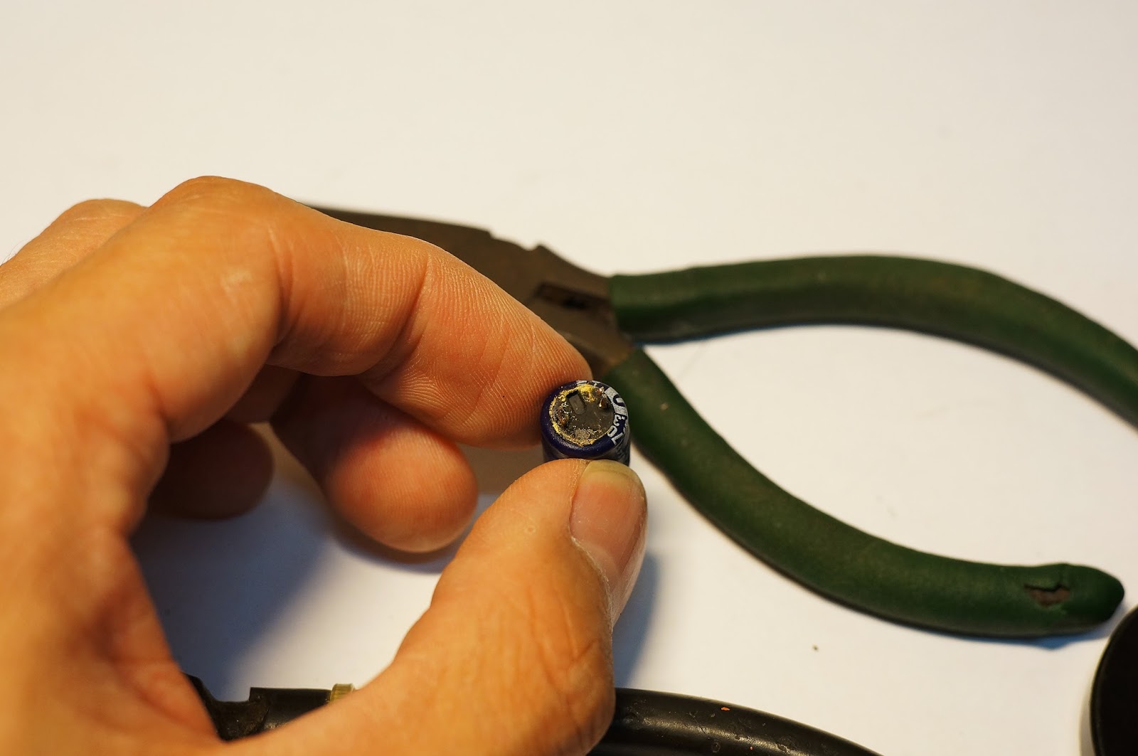
The volume knob is held by a retaining pin that can be simply pulled out and the whole knob can be taken out of the box. The speaker driver can then be removed by lightly (or violently, depending on how warped the wood box is after 90 years) tapping on the two screws at the back.


 |
| It is time for you to retire! |
The back of the speaker driver holds the two (irremovable) screws that can still be used because they are needed to hold the horn in place to the box. The screws have been rusted shut, but a little machine oil left to seep in for 5 minutes helped make the task a lot easier.

So that is a complete teardown of the speaker. I intend to make this into a self-powered speaker with a rechargeable battery similar to the Gramovox above, but without the fancy bluetooth feature (perhaps in the future). I did my research and found many possible components I can fit inside from sites such as Adafruit where they have a Class D amplifier breakout board together with a USB/DC battery charger that I can hook up together.
 |
| Image from Adafruit and for your reference only, click to go to their website |
 |
| Image from Adafruit and for your reference only, click to go to their website |
 |
| Image from Adafruit and for your reference only, click to go to their website |
So what then? Well, thankfully, the best small speakers (according to several reviews on the internet) is made right here in Singapore and it is the X-Mini Capsule speaker and it is readily available in all the shops here.
 |
| Okay.. readily available except in the black color that I wanted it but heck.. |

The X-Mini is a very common portable speaker that has been around for quite some time now. It has an expandable accordion baffle in the middle that gives the speaker a lot more air volume to work with so the relatively small 40mm driver sound a lot better and louder than it should and so I felt it was very ideal for this current project. The best part is that it has a complete circuit built in, so there's no need for me to design a battery charging circuit with an amplifier with a speaker.. this single device combines everything I intended to build into one small capsule that would (most probably) outperform any speaker I source to use in this project.
The speaker is pretty easy to take apart as well. Remove the four screws on the bottom part of the accordion and the base will drop out, revealing the PCB.

Remove the one screw on the PCB and everything will be exposed. I had no need to modify the upper half of the speaker where the driver is so I left that on its own. I planned to remove the switch, potentiometer and 3.5mm plug and extend it out of the box so I would be able to power on and off the speaker, adjust the volume, and plug in whatever music player I want to without opening the box to do so.

I set about desoldering the components from the board, but I found it extremely difficult to do so because the components were mostly soldered on both sides via through holes and they were a real pain to remove. I yanked out the potentiometer together with its traces and I had to improvise with thin strands of wire to rebuild the traces. It wasn't pretty but it works.. hopefully if your project requires you to repurpose the X-Mini like this then you would have a good desoldering tool to help you.
 |
| With the switch removed. The speaker uses a Double Pole Single Throw (DPST) switch but it only actually uses a single pole, thus a simple single pole switch would work. |
 |
| The black tape hides my demolition job on the volume potentiometer traces. They also act as a strain relief so I don't accidentally rip out their tracks again by moving the potentiometer around. |
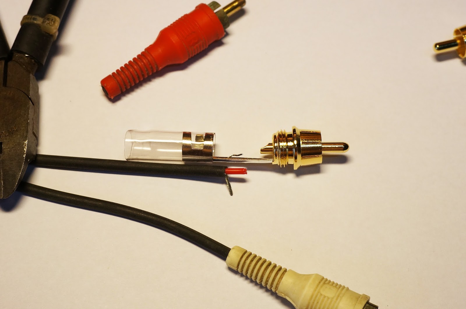
I desoldered the male 3.5mm connector and soldered a female connector at the end of the longer wire. This female connector will be accessible together with the on/off switch on the outside of the box. I also extended the LED indicator so I would be able to see if the speaker is on or off. I did not touch the USB connector that is used for charging the device, but I ordered a microUSB extension (that has yet to arrive) that I will plug into the port on the speaker and fix the female end to the rear of the speaker box.

TLDR; I will eventually be able to access all the features of the X-Mini without needing to open the speaker box, making it a fully portable standalone speaker.
While the speaker has a 40mm driver, the entrance of the horn is a lot smaller at about 18mm. This means that simply placing the speaker at the horn's entrance would result in a lot of sound energy (volume) being wasted because the sound waves do not all enter into the hole.

I basically needed a small horn to guide the sound waves emitted from the X-Mini into the horn's entrance. I found these hard cardboard cones from the shop "Spotlight" where they sell all sorts of handicraft materials and cut it down to size:


I made a simple recording of the capability of this project with my phone's camera, and I will make a higher quality video when I am finally done with this project.